Types of Gears
This post is a reference for the different types of gears that might be relevant for robotics applications.
Mar 06, 2023This post is a reference for the different types of gears that might be relevant for robotics applications.
Change Gearing Ratio
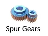
Spur
A cylindrical gear with straight teeth that run parallel to the axis of rotation.
Helical
A cylindrical gear with angled teeth that form a helix shape around the gear.

Internal Gear
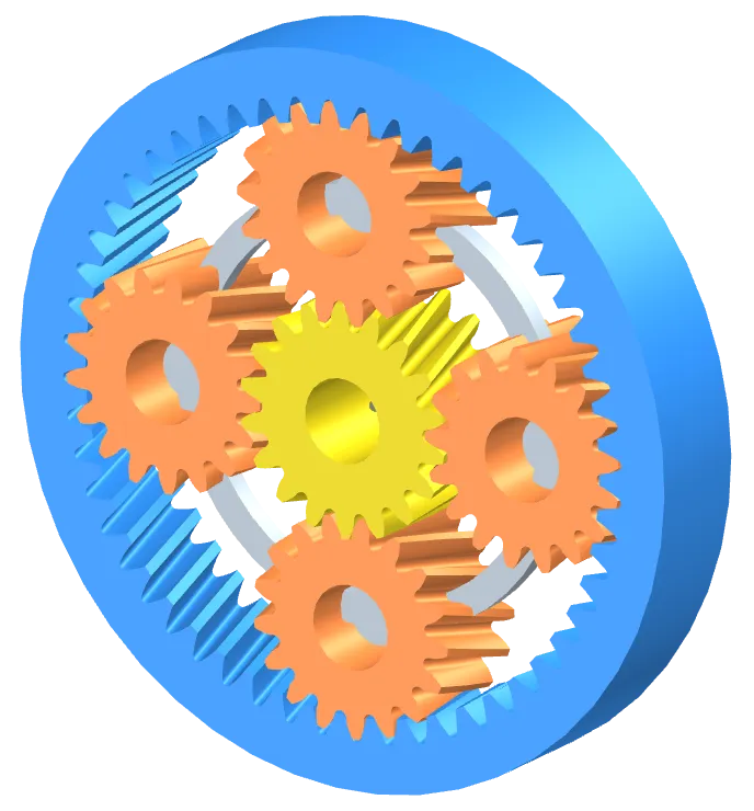
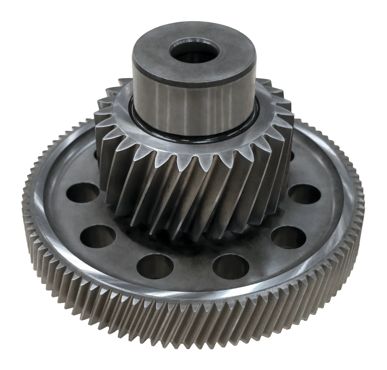
Planetary
A gear system in which multiple gears rotate around a central sun gear to transmit power and torque.
Gearing ratios for planetary gears typically max out around 10:1.
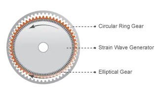
Harmonic Drive / Strain Wave Generator
A harmonic drive is a type of gear system that uses an elliptical flexure to transfer motion between a wave generator and a flexible cup. It offers high gear ratios, high accuracy, and zero backlash, making it useful in applications where precision is important.
The gearing ratio for a harmonic drive can be expressed as r = E / (C - E) where E is the number of teeth on the (outer) circular ring gear and C is the number of teeth on the (inner) elliptical gear.
For example, a gear with 50 outer teeth and 52 inner teeth would have a gearing ratio of 50 / (52 - 50) = 50 / 2 = 25.
Note that the inner axel spins slower than the outer axel.
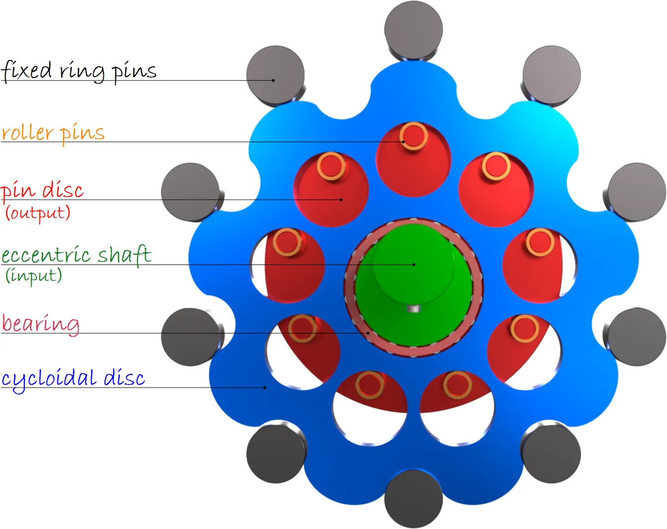
Cycloidal Drive
A cycloidal drive uses an eccentrically mounted cycloidal disc to transfer motion between a input shaft and a rotating output shaft. It offers high torque capacity and low noise, making it useful in industrial machinery.
The gearing ratio for a cycloidal drive can be expressed as r = L / (P - L) where P is the number of (outer) ring pins and L is the number of (inner) roller pins.
For example, a gear with 10 outer pins and 9 inner pins would have a gearing ratio of 9 / (10 - 9) = 9.
Note that the inner axel spins slower than the outer axel.
Cluster
Two coaxial gears glued together. Simple enough to reason about.
Change Direction
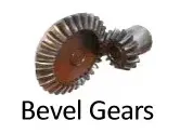
Bevel
A gear with angled teeth that intersect at a point and used to transfer motion between non-parallel shafts.
Right Angle
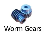
Worm
A gear with a screw-like shape that meshes with a helical gear and is used to transfer motion at a right angle. These are usually used for high torque applications because they have a big gearing ratio.
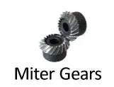
Miter
A type of bevel gear that is designed to transfer power between two shafts that are at a right angle to each other.
Hypoid
A bevel gear with non-intersecting axes and an offset between the shafts.

Rotational to Linear
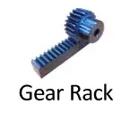
Rack and Pinion
A gear in which a flat bar (the rack) meshes with a gear (the pinion) to convert rotational motion into linear motion.